
TALOS-II PIPE MECHANICS: THROUGHPUT, MERGING & FLOW CONTROL | ENDFIELD

 Razer Kraken Kitty V2Wireless gaming headset with cat ear LED lighting, THX Spatial Audio, and a detachable mic.Shop on Razer.com
Sponsored. We may earn a commission at no extra cost to you.
Table of Contents
Liquid pipe logistics are one of the most misunderstood systems in Talos-II’s Automated Industry Complex. Unlike solid-item conveyors, pipes operate on strict throughput limits and a single-liquid-per-section rule that can devastate your factory output if ignored.
This guide breaks down the math behind pipe throughput, liquid merging, and flow control facilities — so you can build pipe networks that actually deliver the flow rates you need.
TL;DR - Key Points
- Max pipe throughput is exactly 2u/s – each pipe section holds 1u and liquid moves at 2 sections per second
- Only one liquid type per pipe section – mixing requires control facilities to separate flows
- Merged pipes suffer severe throughput penalties – combined flow drops as pipe length increases, especially with 3+ liquids
- Insert control facilities to break long sections – keeps throughput near maximum on merged runs
- Fluid limiters cap throughput passively – preload with 3u of clogger liquid for 0.25u, 0.125u, or 0.083u/s caps
- Control valves auto-reroute on clog – diverts overflow to treatment when main line is blocked
- Fluid manifold trick enables passive priority – no preloading needed for basic overflow routing
1. How Pipes Work
Core Numbers
Every pipe mechanic traces back to four fundamental values:
| Parameter | Value |
|---|---|
| Max pipe throughput | 2u/s |
| Fluid pump output | 1u/s |
| Production facility consumption | 0.5u/s (e.g. Expanded Crucible) |
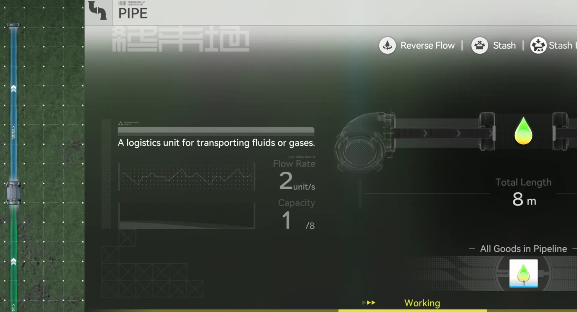
| Liquid flow speed | 2 blocks/s |
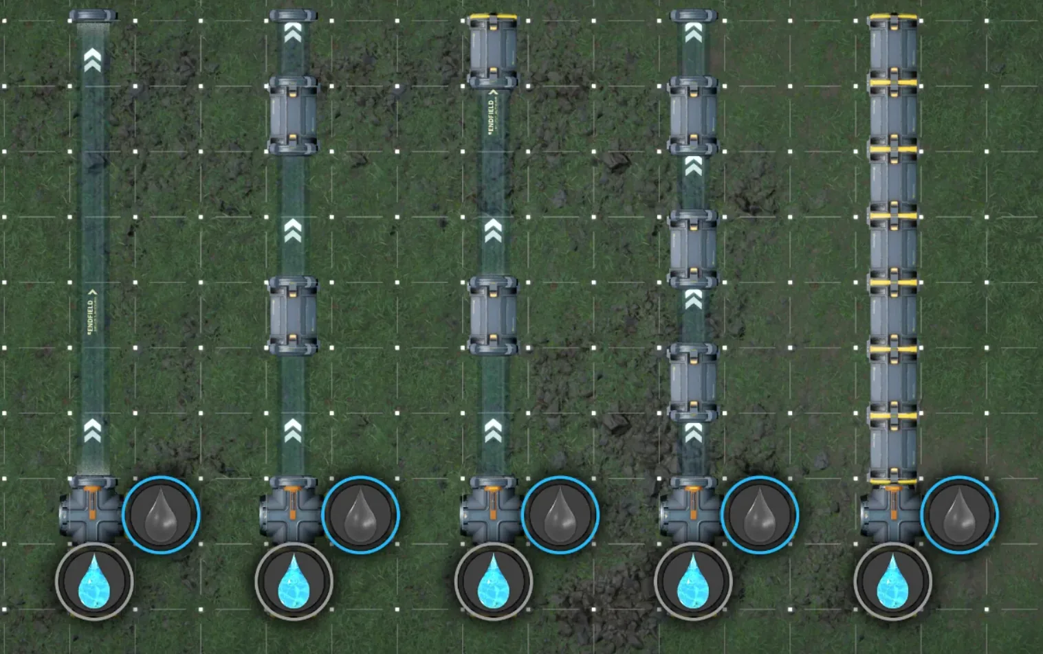
Throughput is exactly 2u/s because each pipe section holds 1u of capacity and liquid travels at 2 sections per second (1u × 2 sections/s = 2u/s).
Pressure Buildup
If liquid piles up at the destination, the pipe runs at full 2u/s capacity even if your source throughput hasn’t increased. The backlog creates pressure that pushes liquid through at maximum rate once the blockage clears.
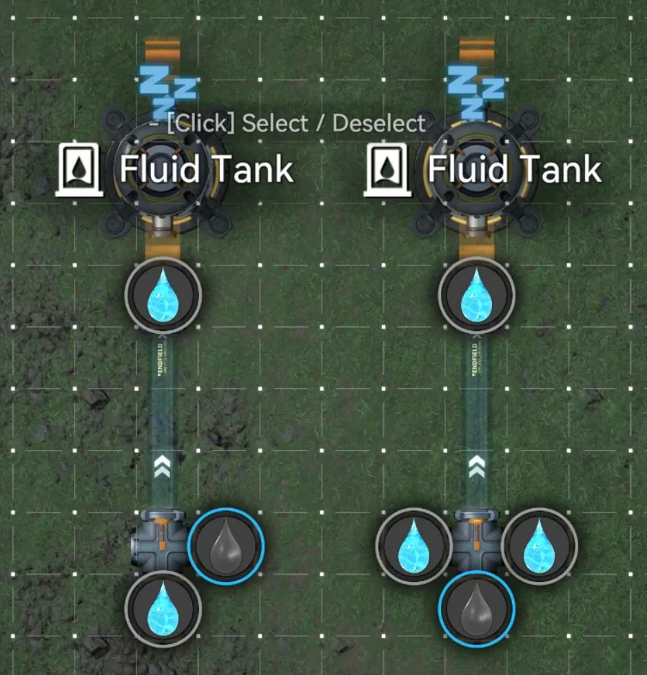
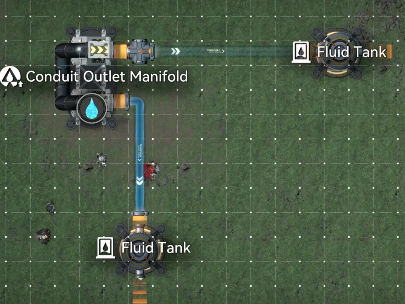
The Critical Rule
Only one type of liquid can exist in a pipe section at a time. Liquids are separated by pipe control facilities. Between two control facilities (or between a control facility and an endpoint), only a single liquid type can flow.
This means when multiple liquids share a pipe run, they must alternate through the shared sections – and this alternation is what causes throughput to degrade on merged lines.
2. Liquid Merging and Throughput
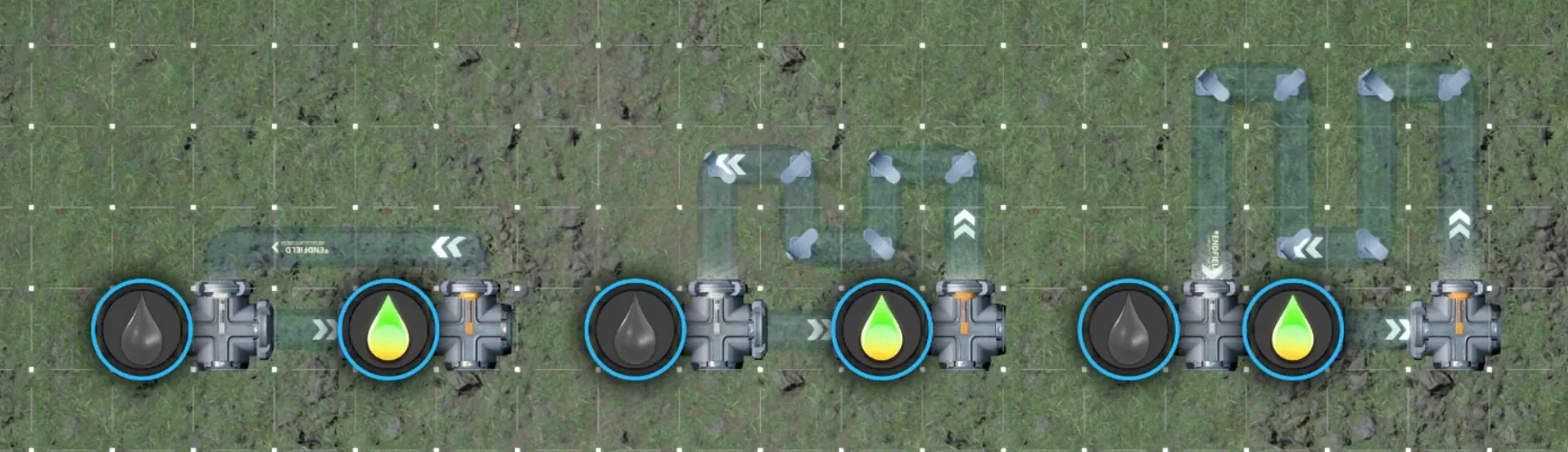
The single-liquid-per-section rule forces liquids to take turns in shared pipe sections. On long merged runs, this can reduce throughput to a fraction of what you need.
2-Liquid Merger Formula
When two liquids share a pipe:
flow per liquid = 2u ÷ 4 ÷ ceil(pipe length ÷ 2) × (pipes with desired liquid)Simplified when each liquid controls exactly 1 pipe section:
flow per liquid = 0.5u ÷ ceil(pipe length ÷ 2)
combined flow   = 1u ÷ ceil(pipe length ÷ 2)
3-Liquid Merger Formula
When three liquids share a pipe:
flow per liquid = 2u ÷ 3 ÷ pipe length
combined flow   = 2u ÷ pipe length
Worked Example (2 Liquids, Pipe Length 3)
| Source | Matching Sections | Flow Rate |
|---|---|---|
| Tank 1 | 1 pipe | 2 ÷ 4 ÷ ceil(3÷2) × 1 = 0.25u/s |
| Tank 2 | 2 pipes | 2 ÷ 4 ÷ ceil(3÷2) × 2 = 0.5u/s |
| Total | 0.75u/s combined |
The liquids alternate: [Liquid A] [Liquid B] [Liquid B] – and the longer the shared run, the worse it gets.
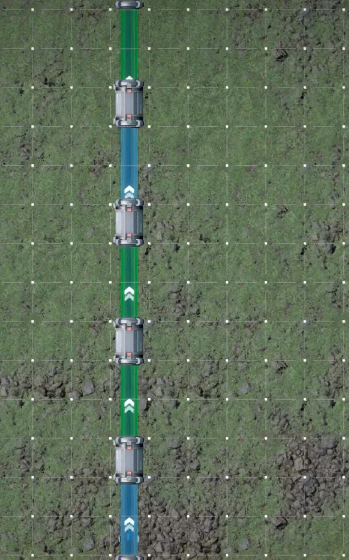
Long-Distance Fix
Insert control facilities along the pipe to break it into shorter sections. With a maximum section length of 2, flow jumps back to 1u/s for a 2-liquid merge regardless of total pipe distance.
This is the key insight: control facilities reset the alternation counter, letting you maintain high throughput over arbitrary distances.
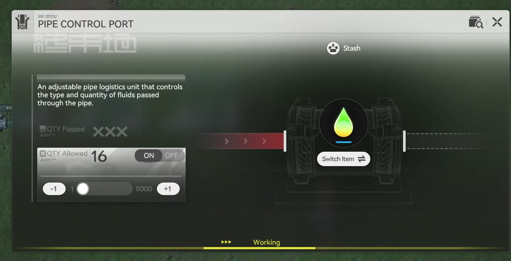
3. Control Valves and Flow Limiters
Fluid Limiters
Flow limiters cap throughput at specific rates for precision feeding:
| Limiter Setting | Throughput | Tank Capacity | Preload Required |
|---|---|---|---|
| 0.25u/s | 0.25u/s | 8u | 3u clogger |
| 0.125u/s | 0.125u/s | 12u | 3u clogger |
| 0.083u/s | 0.083u/s | 16u | 3u clogger |
Setup: Preload with 3u of clogger liquid (jinkao, water, or anything). Precharge the full tank capacity before moving the blueprint – bare pipe liquid disappears on blueprint move.
Community Blueprint (EU): EFO01iOe70347u2AO72U4
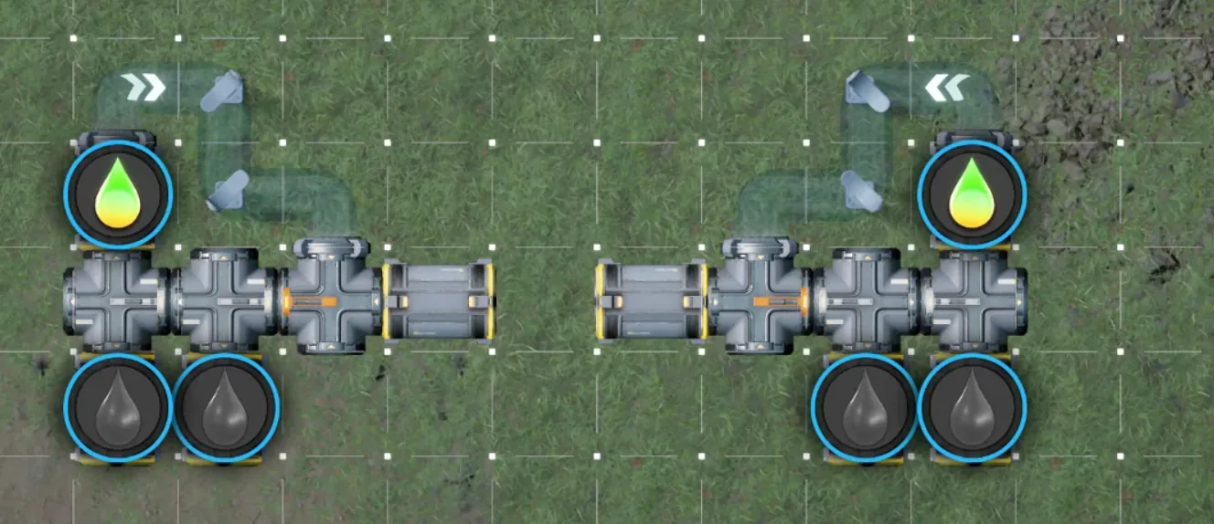
Control Valves (Auto-Reroute)
Control valves automatically divert liquid when the main line clogs:
- Normal state: Main liquid flows to destination
- Clogged state: Overflow diverts to treatment unit
Uses a converger to interleave main liquid and clogger liquid. Requires 5u of clogger preloaded (precharge 9u before moving).
Community Blueprint: EFO01Iao8O768U9Eo5o08
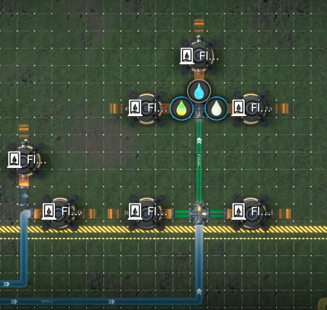
Fluid Manifold Trick (Passive Priority)
A simpler approach using manifolds and a converger for passive priority routing:
- Place a converger next to one manifold pipe
- At ≤2u flow: all liquid goes to the main pipe
- At 3u flow: 2u to main, 1u to secondary
- When main clogs: all flow diverts to secondary
No preloading required. This is the simplest overflow solution for basic priority routing.
4. Testing Your Own Setups
Don’t trust formulas blindly – verify with your own builds:
- Connect a liquid tank + control tank to a water pump
- Measure accumulation rate versus pump baseline
- Compare real throughput against the formulas above
Verified 3-Liquid Formula
Community testing confirms the 3-liquid math:
| Pipe Length | Measured | Formula | Match |
|---|---|---|---|
| 3 sections | 40/180 ≈ 0.222u/s | 2 ÷ 3 ÷ 3 | ✓ |
| 5 sections | 41/306 ≈ 0.134u/s | 2 ÷ 3 ÷ 5 | ✓ |
Final Checklist
- Plan pipe runs with control facilities every 2 sections for merged lines
- Use fluid limiters when facilities need sub-max throughput (0.25u/s, 0.125u/s, 0.083u/s)
- Deploy control valves for automatic overflow rerouting to treatment
- Try the manifold trick for passive priority without preloading
- Test and measure your actual throughput before committing to large builds
Master these pipe mechanics and your Talos-II factory will flow exactly as intended – no more guessing, no more clogged lines, just throughput.

Sponsored. We may earn a commission at no extra cost to you.
Take a Break
Available on desktop